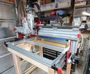
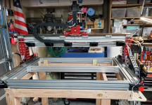
Reconfig of the Carol/Don/Brent CNC or as I like to call it, the Big CDB. Updated -> DONE!

I am NOT knowledgable about this stuff, hence a big reason I didn't want to build a machine.

If I remember correctly Carol ordered from AVID CNC (used to be CNC Router Parts)

But then again maybe not.

Avid Pro package has a heavy duty power supply - one unit serves up tp 5 NEMA34 steppers.

Yeah the one in my machine is huge,

I guess those four and pretty light duty, but ample for one stepper. What is the voltage?
 
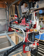
Well, got all the wires (Except for one stepper) and plumbing that is going on the machine installed for now.

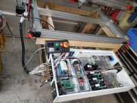
Once I finish up the controller cabinet, I'll trim the cables to length and solder up all of the connectors. My goal is that all components will have some kind of connector going in or out so if I need to maintain the controller, I can disconnect it and put it on a bench to be able to work on it comfortably.

The limit switches work, but I'm not 100% sure about the durability. I may reprint the mounting brackets for them with some protective covers if it becomes an issue.

I will probably be experimenting with the cooling system. It flows ok and I have a radiator on there, but I'm not sure if that's going to be enough throughput. I did mount a thermometer/flow meter on there so I can monitor the temperature and adjust if I have issues.

At this point I'm itching to get this thing working.

The rest of the parts I need to finish it up (as far as I can tell) will be here either saturday or sunday, so it should be getting plugged in next week sometime.

1682122741938.png

1682122769133.png

1682122797898.png
 
Well, been busy with a bunch of spring things over the last month or so and haven't moved all that fast on the CNC but have some time now to work on it.

I haven't done a whole lot with contactors or relays, and like to be cautious on this kind of stuff so have been trying to plan out exactly what the wiring diagrams should look like.

As a side note, I found a nice little 2d drawing app called draw.io that I used for these diagrams that is pretty easy to work with.

I'm going to have an E-stop on my machine that will connect to my controller that should stop it from sending signals to the motors and what not, but I'd also like to have something a little more physical that will cut power to all motors without necessarily slamming off power to the controller. Thats where the contactor will come into play. They say that in order to learn something, you need to be able to explain it, so here goes.

So a basic contactor 120v self holding circuit should look something like this. I'm using the normally open aux contact to keep the contactor energized. Pressing the Go button energizes the coil (A1->A2) engaging the contactor and closing the NO aux on the contactor, therfore keeping the coil energized and holding. Pressing the Stop button opens the circuit, de-energizing the coil and causing the contactor to disengage. In the case of a power outage, it will also cause the contactor to disengage, which would be nice if using to power on other motors.

This is the basic circuit using 120v to power the coil and 120volt momentary Normally closed (NC) and Normally open (NO) buttons.

1687282317253.png

Now that's all fine and good, but I don't really want to run 120 volts out of my control enclosure to a control box. I'd rather use some 12 volt relays and simple momentary buttons to control the circuit.

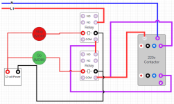
This circuit is functionally the same as the previous one, with the exception of using some remote momentary buttons and 12 volt relays configured as NC and NO in order to operate the contactor.

1687282331717.png
 
Well, been busy with a bunch of spring things over the last month or so and haven't moved all that fast on the CNC but have some time now to work on it.

I haven't done a whole lot with contactors or relays, and like to be cautious on this kind of stuff so have been trying to plan out exactly what the wiring diagrams should look like.

As a side note, I found a nice little 2d drawing app called draw.io that I used for these diagrams that is pretty easy to work with.

I'm going to have an E-stop on my machine that will connect to my controller that should stop it from sending signals to the motors and what not, but I'd also like to have something a little more physical that will cut power to all motors without necessarily slamming off power to the controller. Thats where the contactor will come into play. They say that in order to learn something, you need to be able to explain it, so here goes.

So a basic contactor 120v self holding circuit should look something like this. I'm using the normally open aux contact to keep the contactor energized. Pressing the Go button energizes the coil (A1->A2) engaging the contactor and closing the NO aux on the contactor, therfore keeping the coil energized and holding. Pressing the Stop button opens the circuit, de-energizing the coil and causing the contactor to disengage. In the case of a power outage, it will also cause the contactor to disengage, which would be nice if using to power on other motors.

This is the basic circuit using 120v to power the coil and 120volt momentary Normally closed (NC) and Normally open (NO) buttons.

View attachment 125803

Now that's all fine and good, but I don't really want to run 120 volts out of my control enclosure to a control box. I'd rather use some 12 volt relays and simple momentary buttons to control the circuit.

This circuit is functionally the same as the previous one, with the exception of using some remote momentary buttons and 12 volt relays configured as NC and NO in order to operate the contactor.

View attachment 125804
BRENT the start Button and the stop Button need to be in series, you show them in parallel. Then you need to use a Normally open set of contact from your control relay around the NO start button to seal it in. Then when you push the start button it will energize the control relay and the control relay aux contact will hold the relay energized until the stop push button interrupts the power and drops out the control relay. use a second set of contacts on the control relay to provide 110 volts to the main contactor.
 
I think I see what you're saying, but I think this should work as well.

In the first diagram, the buttons are in series, and the second diagram, the relays are replacing the buttons and are in series.

In the second diagram, Both my buttons are momentary and are being used to activate the relays. Unless I'm missing something, the second diagram is functionally equivalent to the first.

At any rate, I'm going to work on some bench testing on this in a little bit and I'll let you know if I have any issues.
 
The stop button is a Normally closed button.. the botton is a normally open button. Both are momentary make/break button. the top relay will come on right away and drop out when you push the stop button and the bottom relay will stay off until you push the button and will drop out when you let go of the button, You don't need two relay only one is required if you will use the way I have described. This is how it was wired to begin with and it works.
two relay is two things to fail.

K.I.S.S. is my motto.
 
The stop button is a Normally closed button.. the botton is a normally open button. Both are momentary make/break button. the top relay will come on right away and drop out when you push the stop button and the bottom relay will stay off until you push the button and will drop out when you let go of the button, You don't need two relay only one is required if you will use the way I have described. This is how it was wired to begin with and it works.
two relay is two things to fail.
K.I.S.S. is my motto.
I like the idea of a single relay. That does sound like a better solution.

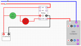
I'm not good at draw.io, but this is my interpretation of how I'd do it using a DPDT relay and 12v to control the 120v for the contactor.
View attachment 125805
Thanks Darren. Now I need to wrap my head around this.

With you and Don helping me, I'm sure I'll get it soon.

I did do a bench test on the first solution with 2 relays and it works fine, just to validate what I was doing, but it would be nice to do it in a more simple way. Was nice that it worked the first time and nothing blew up or made me say bad words 🤪


Ok, Back to the drawing board for round 2. Be back later.
 
ok, I may be slow, but I'm persistent and having fun working on these circuits.

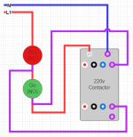
So worked up this diagram.

This one will cause the relay to self hold, which in turn will energize the coil on the contactor.

Pressing the Go button will energize the relay, and connect the positive 12 volt through then NO terminal to the COM terminal through the Stop button which will keep the relay energized on.

Pressing Stop will break the circuit, causing the relay to become de-energized.

It's then a simple matter of connecting L1 to the other side of the relay on the NO contact, through com, connected to A1, and Neutral to A2

I think struggling through this has helped me have a better understanding of how I can use relays for future use, so this has been good.

1687294885640.png

So, There you have it. That seems to work fine as well, but with one relay and much simpler.

 
Last edited:
Getting pretty close. All done (I hope) Soldering aircraft connectors. Ended up needing one more for the control box, didn't feel like redoing the panel for them, so created a little plug to run the wires through.

Still need to connect the limit switches and a few other assorted wires for the control box.

Should be able to connect power soon, but it's getting warm and its the first day It's been 'poolable' in weeks, so I'm grabbing a cold one and headed out to clean up the pool.

1688074380244.png
 
Top