Mech Rm Remodel

Bill Satko

Member
Messages
3,223
Location
Methow Valley
A.K.A the "Temp Pottery Studio". I have decided to consolidate some pictures and information that I have already posted via the weekly "Friday" threads. I will then update this thread with additional progress.

First some background on the room. It is a mechanical room that resides under the house with only an exterior door for access. It is roughly 12' x 18 with a height of 9'4". This height is compromised somewhat with support beams, plumbing lines and hydronic piping. Still, it feels quite spacious and not restrictive at all.

This room was dug out at one corner of the house and has concrete walls almost to the ceiling along all four sides. They used a lot of concrete in building this house, which amazes me considering how remote it is. The house sits on a minimum of 2' high above ground stem walls. This is snow country and you can expect to have snow laying against the house walls. What you normally see with houses around here is a short concrete stem wall above ground and about 3' of metal siding to keep the snow away from the wood. This would be an extremely expensive house to build now days.

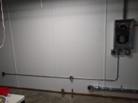
The interior of the room was completely covered with 2" of grey rigid insulation. Not a very appealing look but probably sufficient for a mech room. But not for a temporary pottery studio...according to my client. She wanted something to cover up the insulation. Something nice and white. I tried finding some easy way to appease her but the best recourse was installing OSB sheets to the walls. There was a lot of things either mounted to or penetrating the walls. This was not going to be easy and we decided to only do one long wall and part of another at this time. Just to get her set up and running.

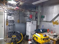
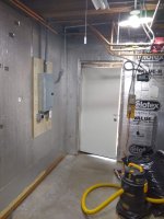
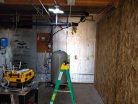
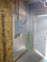
The room contains a oil fired hot water boiler for hydronic heating system, an oil tank, an electric hot water heater (the hot water boiler also included domestic hot water) and a well pressure tank. In addition there is as I mentioned before all the piping associated with all of this. Here are some pictures of what it looks like before I really got started. The next post will detail installing the OSB and how I did that.
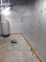
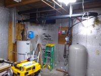
IMG_20221010_114636103.jpg

IMG_20221010_114642729.jpg

IMG_20221010_114649607.jpg

IMG_20221010_114655997.jpg
 
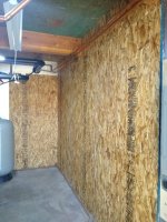
I really struggled in coming up with some simple way to cover the rigid insulation panels to make them look better. At first I thought to go with 8' x 4', 1/16" thick white poly wall plastic panel that I would contact cement to the surface. I actual bought a single sheet, but after getting it home and realizing how floppy it was I didn't believe I could pull it off. A memory of a "I Love Lucy" skit where they attempt to wallpaper a room kept playing in my mind. Besides, I wanted to be able to mount something to wall. Now ideally I would build a stud wall and panel that with something, but didn't want to go that route. I figured as long as I didn't need to secure anything heavy to the wall, I would anchor OSB board through the insulation and into the concrete.

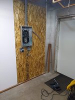
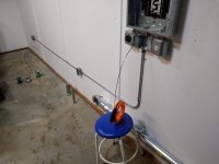
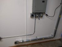
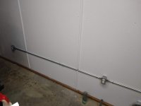
That is what I did using my Bosch SDS Rotary Hammer Drill and long tapcon concrete screws. First I installed 2" x 2" pressure treated wood on the floor for the OSB to sit on. I worried that if there was water on floor, the OSB would soak it up and create problems. In addition to screwing the panels to the insulation I also used construction glue. It was difficult but I managed to drill out or cut out for the existing penetrations. The only one that would really be difficult would be the new sub-panel I had installed last winter. In fact we installed 5 panels; installed trim at the seams and painted them before tackling this last panel.

I had to pull back the wiring/conduit that ran outside through a core drilled hole in the concrete wall over to our new heat pump for the mini-splits. I then removed the subpanel from the existing plywood that was screwed through insulation into the concrete wall. I propped the subpanel up while removing the existing plywood and then slid my sheet of OSB under it and remounted the panel. I then re-wired everything. In addition to the conduit/wiring that went out through this hole in the wall was a 1/2" PVC vent line from the oil tank. I also had to remove this and reinstall it after the panel was installed.

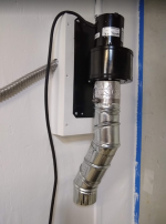
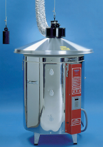
This hole to the outside was my only avenue for a vent I wanted to run for the pottery kiln. This vent is for removing fumes from the kiln so that it does not get into our living space. 3 small holes are drilled in the center of the kiln bottom and a special cup fits over on the outside of these holes. A hose or ductwork then runs from this cup to a fan that exhaust it to the outside. A few holes are also drilled in the top of the kiln to allow for air movement through the kiln. This venting will not do anything for keeping the heat of the kiln from warming up the room. We may be putting a hood above the kiln to do that. That is another project for another time.

I had to build a box to allow the fan to mounted and still allow for the conduit and oil tank vent to co-exist.

Next post will be about wiring in 3 new outlets for the room.

IMG_20221013_150249458.jpg

IMG_20221015_141053974.jpg

IMG_20221015_141105118.jpg

IMG_20221118_151413163.jpg

1671141464885.png

1671141525815.png
 

Attachments

  • 1671141408576.png
    1671141408576.png
    519.3 KB · Views: 2
  • 1671141212181.png
    1671141212181.png
    519.3 KB · Views: 2
The existing mechanical room had limited outlets. Basically only one outlet near the door. Last winter I had the A/C installer's electrician put in a 100 amp subpanel in this room and then run the power to the heat pump from there. I also had him put in breakers and outlets for 50A 220 volt circuit and a 20 amp 220 circuit. The 50 amp was for the kiln. I had planned all along to run a 120 volt circuit for those items like her pottery wheel, kiln exhaust fan and any electric hand tools.

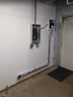
I decided to install an all in one circuit breaker (AFCI and GFCI) for this. I wasn't sure if local codes would make me comply with AFCI requirements and really I didn't care as I thought it a good idea anyway. I put in a box right at the panel and another two along the same wall down low. Running the EMT conduit was easy as I used conduit fittings (box offsets and 90 ell), instead of bending them myself. Pulling the wire was also easy as it was a short run.

I pulled a grounded conductor. I did this as I noticed that the electrician had also pulled a grounded conductor. I really had no idea if local codes now required this instead of relying on the EMT as a ground. I just didn't want to have the inspector come and shoot down my install because of that and now require another inspection and more money.

And that brings up the fact that I pulled a permit for this work. Here in Washington state and the county I live in as a homeowner I am allowed to do my own work. Obviously this is really a small job and maybe others would not have bothered by I did for two reasons. One, I didn't want to invalidate my house insurance. And 2nd, I am not an electrician and welcome someone looking at my installation. I believe very strongly I got it right but that has not stopped me in the past of making mistakes.

Work will continue on this remodel to make the room nicer, mainly skinning the rest of the room and adding more lighting. Now I am in a holding pattern as my wife organizes her clay stuff. I donated my rolling tool boxes for her to organize her things. Not having a real shop or garage yet, I am going in another direction with some tool storage. More portable. I am reconfiguring everything into Milwaukee's packout system. Once she clears space from bins into the tool box. I will install standing shelving we bought (cheaper than materials I could buy) and I will also assemble her slab roller we had packed away.

IMG_20221212_144908061.jpg

IMG_20221213_132824248.jpg

IMG_20221215_104339827.jpg

IMG_20221215_104344245.jpg
 
Last edited:
I pulled a grounded conductor. I did this as I noticed that the electrician had also pulled a grounded conductor. I really had no idea if local codes now required this instead of relying on the EMT as a ground.

I think it is, in at least some installs (code on this has moved around some relatively recently the 2008 revision at least changed grounding rules a fair bit and I think the couple revs past that have tightened it even more).

It's a good idea anyway IMHO, it's hard to over-ground things (unless you create loops which is bad for other reasons.. but this doesn't do that).

Is that an intumescent paint on the wall? I would be tempted to at least use that around the kiln without a drywall or similar fire resistant skin..

Looking good!
 
I always pull a ground, I've worked in commercial construction where I've found conduit joints to be loose or the lock rings off or even left off.

Edit: I also wondered about using a non-flammable material behind the kiln, such as concrete board or corrugated metal siding.
 
Besides the kiln exhaust, is there a room exhaust fan? Guessing it will get pretty warm in there when that kiln is going.
No, only the exhaust fan associated with duct that goes to the bottom of kiln. This summer we will probably be installing a hood over the kiln and attaching it to the current exhaust fan. Also I have told her that she needs to make sure the oil fired boiler is off when using the kiln and fan. Don't negative pressure in the room while the oil burner is firing. Of course during the summer we don't have the boiler running.

1671223382062.png
 
Is that an intumescent paint on the wall? I would be tempted to at least use that around the kiln without a drywall or similar fire resistant skin..
Edit: I also wondered about using a non-flammable material behind the kiln, such as concrete board or corrugated metal siding.
The kiln is on wheels and will rolled away from the wall during firing. The kiln instructions say you only need 18" from a normal wall.
 
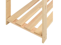
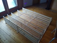
I did some woodworking yesterday! Well, kind of. We bought an relatively inexpensive pine storage rack for my wife's pottery studio. I could have bought the materials and made it myself for less money, but only if I devalued the time it would take for me to make it. Plus, avoiding the foot tapping from a certain someone while I got around to it, made it priceless.

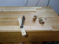
I was impressed with the quality of the wood. I thought it would zip together in no time at all. Well, I was a little wrong about that. As you can see below the shelves fit into a dado on the "posts". Only problem I found was all of the dadoes were exactly 1/32" too narrow. All of them. Thankfully I didn't just try a bigger hammer. I had two ways to fix it. Narrow the shelving by chamfer the edges or widening the dados on the posts. I went with the latter by using my side rabbet planes. You don't need them often, but they work well when you do.

All this makes me wonder what your normal person would do when they received this to assembly. I got to think there would be a lot of upset people. How would they fix this?

1671372412048.png

IMG_20221217_144525636.jpg

IMG_20221217_144453156.jpg
 
Top