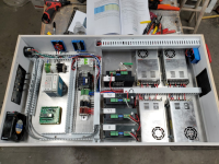
Reconfig of the Carol/Don/Brent CNC or as I like to call it, the Big CDB. Updated -> DONE!

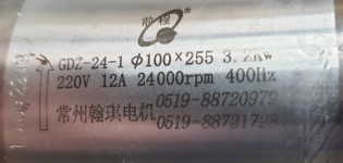
Sweet - I am pretty sure that is the same spindle as I have

I helped Carol get it from my Chinese contact.
It is a really nice spindle

Here is a really nice drill chuck with a 1/2 shank.

I drilled a series of holes with it yesterday.
Not the first time using it,

Hmm, so the spindle has a Morse taper in it? Very interesting.

Trying to find a manual or spec sheet on it but not much luck.

1680369793974.png
 
Brent I just remembered something that I had thought about. The Z axis has a lot more travel then you will ever need with the existing riser blocks. I think you might want to consider getting longer extrusion to take advantage to this I believe the ball screw has either 12 or 14 inches of travel but the risers on it only allow 8 inches of it to be used so by replacing them you can gain as much as 4 inches of height in the Z axis. JMHO It would be easier to do it now rather than later.
 
Brent I just remembered something that I had thought about. The Z axis has a lot more travel then you will ever need with the existing riser blocks. I think you might want to consider getting longer extrusion to take advantage to this I believe the ball screw has either 12 or 14 inches of travel but the risers on it only allow 8 inches of it to be used so by replacing them you can gain as much as 4 inches of height in the Z axis. JMHO It would be easier to do it now rather than later.
I did notice that. I was thinking that might come in handy for keeping the rotary axis installed below the level of the spoil board, so that I could go down lower to take advantage of that on the rotary, but I also like the idea of the taller risers. I am thinking about converting it to a 4'x4', or even a 4'x8' someday. I'm going to try and get things wrapped up and running this week, if USPS ever delivers my controller board. It's been stuck 'on the way' from kent WA for the past 3 days, so...
 
Not much progress lately due to winter hanging on and on and on. Been too cold to work out in the garage, but I've been getting parts in stock.

One other activity I undertook was to try and learn Fusion 360 for designing 3d printed parts. I've always wanted to learn it, but finally took the time yesterday.

I went through these tutorials by Fusion 360 Basic Tutorials by Arnold Rowntree. I found his tutorials to be clear and concise and fast enough without a whole lot of extraneous jibber jabber that I was able to follow through on all 16. I feel like I got to a basic enough level that I'm able to use it now to design my own simple parts. Basically just competent enough to be able to do what I've done in sketchup before.

I will say now that I've gone through the tutorials, I can see how some of the things I did in sketchup are similar. I would often create groups/components and connect those together in sketchup. That kind of paradigm matches up to how everything starts with a sketch in F360.

Why did I switch? Well, I'm still using an old desktop version of sketchup and depended on a few plugins for 3d printing. I liked the 3d warehouse in SU, but access to that was shut off for the version of sketchup I had. I think that's what really triggered me to try F360. I still like SU, but I can see the advantages of using F360 going forward.

What I like about it so far is:
1) It's more like creating a recipe. With the proper constraints, you can go back and change the size of one part and it will automatically resize the entire project.
I'm looking forward to being able to create parametric models where you can just change a few parameters to affect the entire way a model is built.
2) It's easy to go back and modify just sections of a model through the 'timeline' function.
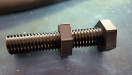
3) Threads. It has a built in library of thread sizes that you can use for designing threaded objects and it's ridiculously easy to use them.

Sample bolt I made just for kicks.
1680894042593.png

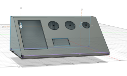
Here is a control panel I drew up in a couple hours. Granted, I could have knocked it out much faster in Sketchup, but that's because I still have a lot to learn. Next time should go much faster.
1680893251414.png
 
Hmm, so the spindle has a Morse taper in it? Very interesting.

Brent - no it is not a morse taper.

The spindle does have a taper but it is for the ER collets

The drill chuck I linked to has a straight 1/2 shank.
It will fit into an ER20 1/2 collet.

Drills don't generally have standard shank diameters.
The shank is whatever the drill diameter is.
A drill chuck is kinda decessary if you want to do any drilling.
 
Crap, 10 days since my last post? What the heck. Weather, and other things have been keeping me busy, as well as waiting on supplies to show up.

I did have to solder up the control board, which wasn't that bad. You can see the little brains of the outfit down in the lower left there.

At any rate, here we are. I did get a good deal of work done on the wiring today, with a fair amount of crimping and soldering going on.

1681871486684.png

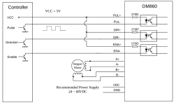
The one thing that made me stop for the day, other than working on it for 10 hours, was getting to the point of hooking up the stepper drivers to the controller. They way it looked like when Don had it working was that he only needed to use 4 of the pins on the input connectors, and somehow had that connected to 2 pins per axis that fed into a connector board.

So, I looked at my OX, and sure enough, It follows this pattern. I have the VCC Daisy chained to the pul+, dir+, and ena+ and only using 3 signals from the control board. I have one 5v vcc+ going to the 4 stepper drivers on the ox.
1681872158584.png

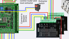
So I look at the documentation for the grblhal board, and it shows the ground being daisy chained to the ena-, dir-, and pul-, with the 3 other signals going to the 'pluses'

1681872337548.png

But, At this point calling it a night and will do some more thorough research tomorrow.
 
So I look at the documentation for the grblhal board, and it shows the ground being daisy chained to the ena-, dir-, and pul-, with the 3 other signals going to the 'pluses'

View attachment 124971

But, At this point calling it a night and will do some more thorough research tomorrow.
I looked up mine and it is wired the same, ground going to the negative side of step/direction/enable
 
Top